We have just said that the sludge filter press is a machine whose purpose is precisely to provide for the dehydration of fluids (more commonly called sludge) of civil and industrial or process origin.
Unlike other devices used in the industrial field (tape press, centrifuge, etc.), the filter press has the characteristic of being a discontinuous machine, i.e., during the filtration phase a finite volume of sludge or more generally of fluid is processed dehydrate.
Already from this difference, it has no real basis to talk about the hourly flow rate processed, but we should talk about the flow rate per filtration phase.
The sizing of the sludge filter press is done once the filterability characteristics of the sludge to be processed are known and on the basis of this data, the filtering volume that the machine must make available to dispose of a certain flow rate can be traced back.
The filterability characteristics of the sludge can vary greatly between one type and another and in general only a laboratory test can provide these data. Where it is not possible to carry out these tests (think for example of the case in which a plant is being designed) we rely on the experience of the manufacturer or we go by analogy with other similar cases.
There are cases in which the filtration lasts 3 or 4 hours (for example biological sludge), others in which inert materials or very heavy fluids are treated (for example lead pastel) in which the cycle is very fast (15/20 minutes) or still other cases in which in particular industrial processes of concentration the cycle can last even 7/8 hours and finally other shorter cycles 1.5-2 hours if we think for example of the cases of sludge containing aluminium hydroxides.
The filterability of the sludge is therefore the key data from which to start to arrive at the sizing of the filter press.
The other parameters that need to be considered for correct sizing are:
– Hourly flow rate of sludge to be processed
-% of dry solid contained in the sludge
– Density of the inlet sludge
-Amount of hours/day of operation of the filter press
– Desired degree of automation (automatic, manual)
With these data, it is possible to proceed with a mass balance to correctly size the filter press for the chosen process.
Let’s see this example:
– Hourly inlet sludge flow rate: 1.25 m3/h
-3% SS of solid substance in the sludge
-Inlet sludge density: 1.1 Kg/dmc
-Sludge production hours: 8 h/day
Qf in = 1.25 m3/h*8h/day = 10 m3/day – daily flow rate of sludge to be disposed of.
Pf in = 10 mc/day*1.1 Kg/dmc = 10 mc/day*1100 Kg/mc = 11000 Kg/day sludge
Of this sludge, the solid content is 3%
Pf SS = 11000 Kg/day * 3% = 330 Kg/day of sludge
While the remainder is liquid fraction.
Summing up:
Pf in = 11000 Kg/day of which: Pf SS = 330 Kg/day + Pf L = 10670 Kg/day.
Let’s suppose that the output density of the sludge that can be obtained with the filtration process is 30%.
With a simple mass balance, we have that the solid content found in the previous step now represents 30% by mass (we find it again in the panel):
Pp out = 330 Kg/day / 30% = 1100 Kg/day
In summary, the panel (or cake) is made up as follows:
Pp out = 1100 Kg/day of which PSS = 330 Kg/day, while PL out = 770 Kg/day
If we assume (either by calculation or following experimental tests) that the density of the waste cake is equal to 1.4 Kg/dmc, we obtain the volume of the cake:
1100 Kg/day / 1.4 Kg/dmc = 785.7 dmc/day
The filter press must dispose of a volume of cake equal to 785.7 dmc in one day.
Let’s assume that the filtration system works for 8 h/day and that a filtration process (including filling, filtration, opening and various options) lasts 4 h:
nf = 8 h/day / 4h/filtered = 2 filtered/day
Vf = 785.7 dmc/2 = 392.85 dmc (volume of the filter press).
The volume of the sludge filter press must therefore be approximately 393 dmc.
At this point it is necessary to find the size and number of filter plates, keeping in mind the process in which this machine will be inserted.
Let’s take for example a filter plate of size 1000×1000 – chamber thickness 25 mm.
Here are the data of this plate:
Vp = 19.7 dmc (volume of the filter chamber)
Sp = 153.1 dm2 (filtering surface)
The number of filter chambers will be:
nc = 393 dmc / 19.7 dmc = 19.94: 20 filter chambers
Since n filter chambers are formed by n+1 plates, the filter press in question will be:
1000×1000 – 25 mm chamber / 21 filter plates.
Vf = 20 * 19.7 = 394 dmc (filter volume)
Sf = filtering surface = 20 * 153.1 = 30.62 m2
Naturally this is an example where the parameters have been assumed for simplification purposes.
However, some technical and economic considerations can be made:
-Increasing the volume of each filtering chamber (obtained between one plate and the adjacent one) will result in fewer plates and therefore in general a reduction in costs
– However, it is not always possible to do this, as the filterability of the sludge must be considered: using a smaller filter chamber allows the more difficult (less drainable) sludge to filter better.
– By decreasing the number of plates, the total filtering surface also decreases and therefore the filterability of the fluid.
-It is possible to obtain the same filtering volume by also changing the size of the filter press: instead of for example a 1000×1000 filter press – 25 mm chamber / 21 plates, the same volume could be obtained with an 800×800 machine – 25 mm / 34 chamber plates.
These dimensional data must then be crossed with the degree of automation desired (semi-automatic – fully automatic) and precisely the type of process and available options; but in general, the rough calculation that can be made for sizing the filter press is the one just shown.
However, the fundamental thing is to understand that the sizing of the sludge filter press is a mass balance.
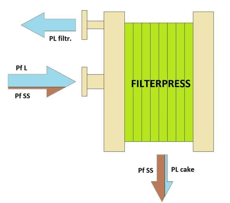
In terms of calculation, I must always consider that the solid part of the incoming sludge will concentrate at the outlet, with a cake (also called cake) which will contain a higher percentage of suspended solids than the one at the inlet, while in the discharge of the filtrate I will tend to have only the liquid part.
Therefore, by adding the liquid part of the filtrate discharge to the liquid part contained in the cake, I will have to obtain the liquid part contained in the incoming sludge, while the solid part will be completely transferred to the residual cake.